Walls tab
|
|
Walls tab |
Top Previous Next |
|
|
The walls tab allows the user to add or modify a host of building features with just a few mouse clicks. Select from a variety of end wall frame conditions including bearing frame (default), hot-rolled rafter, non-expandable rigid frame or expandable rigid frame.
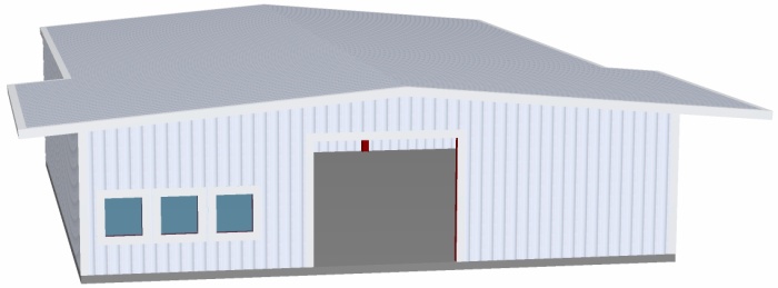
A standard box building generally has bearing frame end walls. The bearing frame end wall consists of vertical columns that support the rafters. This type of end wall is also known as “post and beam” or non-expandable end wall.
A hot-rolled rafter end wall utilizes a standard wide flange beam (I-beam) section as the rafter; this allows more headroom above the door. By setting directly on top of the end wall columns, instead of fastened to the back of the columns as would occur with a cold formed CEE rafter, the hot-rolled rafter allows for unobstructed clearance from the door header to the underside of the roof purlins. Note: If a lean-to building is attaching to the building we require a minimum of hot-rolled rafter for end wall frame that will have attaching lean-to building(s). We will NOT design a lean-to building using a cold-formed rafter (standard bearing frame).
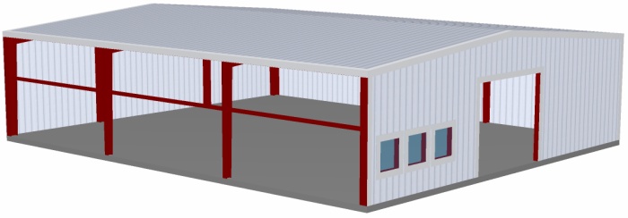
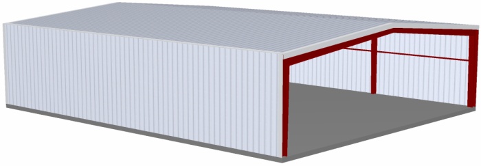
A non-expandable rigid frame is normally used when large or multiple doors or windows are placed in an end wall. IQS calculates the capacity of the end wall frame types and designs the appropriate end wall frame type required. If there are specific requirements that you desire you may input them, but please remember that if IQS detects that the end wall condition fails structurally, the program will automatically design an end wall to ensure proper design. Roof only buildings will have a non-expandable rigid frame unless the user specifies fully loaded. We suggest using a non-expandable rigid frame if there is a lean-to building attaching at the corner of the side/end wall.
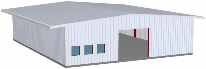
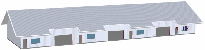
An expandable rigid frame is used primarily when future expansion is desired. All hangar door buildings are designed utilizing a properly loaded rigid frame. In the case of the hangar door, the rigid frame is not considered expandable unless the hangar door system is removed, allowing the building to be expanded. Users can add side wall and gable roof extensions to one or all sides of a building by mouse clicking or entering the desired size in the Roof Extension box. Sizes can vary per wall and soffit can be excluded by un-checking the “Include Soffit” checkbox. Note: Buildings have no roof extension by default. If desired, they will need to be added. The sample building below has 4 foot roof extensions on all sides. Maximum extensions are 8 ft for left and right end wall, and 5 ft for front and back sidewall.
The Open feature allows for complete removal of any wall of the building. If the wall is to remain open permanently you must select Partially Sheeted To Remain Open under the “Type” option of the Building tab. If the wall is designed to be enclosed “By Others” IQS assumes that the wall system will be self supporting and NO lateral support of the wall is allowed. If the wall system being added by others requires lateral support please contact your salesperson for a special quote. Note: future plans for IQS will allow the user to design a Spandrel Beam that will carry the entire or partial wall load.
Users can use the option button to specify more details on the walls than shown in the options tab:
See here for more details on the left and right wall options (end wall options), and here for the front and back wall options (side wall options).
Select from bracing types including Panel Shear (default), Diagonal Bracing, Wind Column or Portal Framing. Users can specify the type of bracing desired, or the minimum they desire. However if IQS detects there is not sufficient bracing, the program will add bracing to satisfy the requirement. Example: if a user specifies cable bracing, and there is not a sufficient number of bays that can be braced the program will attempt to place any number of combinations of bracing until the bracing requirement is met. If a user chooses diagonal bracing and a door opening is placed in every side wall bay the program will attempt to use one or more portal frames. In the event there is not enough room above the doors to ensure proper headroom clearance, the program will utilize one or more wind columns to meet the bracing requirement.
End wall bracing is seldom used. There are many reasons IQS will not design using diagonal bracing in an end wall. Slots are required in the secondary framing to allow for diagonal bracing, thus weakening the girts and it is our interpretation that the end wall typically suffers the most from wind loading, and we do not use diagonal bracing in end walls with a flush girt condition. If IQS detects that there is not sufficient available panel shear, the program will select the minimum sized rigid frame to satisfy the design requirement. IQS will design the roof system (secondary framing) in the most optimized manner. Roof purlins are automatically sized and spaced; however, they can be manually spaced as necessary. If alternate roofing material is desired, i.e. shingles over plywood, then select the required spacing and add the material weight to the dead load on the Building Tab. Note: peak spacing should be set to a minimum distance if wood sheeting is used for the roof material. To specify a specific panel shear capacity for materials supplied by others please contact your salesperson. Options available are to include the soffit; the exterior panel applied to the underside of roof extensions, if applicable.
|
| © 2006-2007 ICON Buildings |